
Ultimate stepper motor cooling (sub-optimal cleanup and wire management).It’s no secret that stepper motors, and the drivers that push them, can get H-O-T. I’m talking hot enough to burn you in short order if you touch them. Hot enough to melt ABS and PETG, which is quite often the material used to make motor mounts in 3D printing. It will be hard to print replacement mounts if you’ve already melted the ones currently holding your motors, so let’s see how to prevent that in the first place. Skip to the fun, overkill portion!
Passive Cooling
Most stepper drivers come with heat sinks these days. Use them! Have you ever accidentally touched the top of a CPU that was in use? Insta-burn, right? Same thing with these guys. Help them out by spending the 90 seconds to attach the provided heat sinks to all 4 (or 5) drivers. It dips into the realm of active cooling, but I’d strongly suggest adding a fan (80-120mm) pointed at the top of the board to help keep the drivers and other components cool. There are also heat sinks for the motors themselves, but we’ll get to those later.
Current
Before running your printer in earnest, you should always optimize the amount of current you feed your motors. In general, use the minimum current necessary to reliably move and hold the load (i.e., no missed steps). My typical approach is fairly simple:
- Slowly lower the current until the motor “sounds bad” or the movement is no longer consistent/reliable.
- Raise the current back up 0.25A to make sure you’re not right on the edge of what’s required to keep things moving.
- Run some break-in G-code or movement tests, starting slow (~50mm/s), and ramping up to a fairly high speed (~200-250mm/s) and acceleration (at least 3000mm/s2) for about 15 minutes. The easiest way to do this is to set your G-Code to run at something such as 166.67mm/s, but back your feed rate down via your LCD or printer software to start your print at 50mm/s (30% of 166.67) and increase the feed rate by 10% every minute or so until you’re at 250mm/s (150% of 166.67). The goal is to get the motors working fairly hard so we can monitor their performance and temperature.
- Periodically check the temperature of the:
Drivers – Very briefly (at first) touch the top of the heat sinks for the drivers in use. They should be warm, but ideally you should be able to hold your fingers on them without being burned if your current is correct.
Motors – Same as above. Briefly touch the case of the motor. Expect it to be warm, but you should be able to grab it and hold it without being burned.
Obviously, all board, driver, motor, and load combinations are different, so your mileage may vary. The core tenet is: cooler is better as long as the motors are getting the job done.
Side Note
This is where a digipot current adjustment is super nice. With Smoothieware and a digipot current control compatible controller board and drivers, this can be handled as easily (and repeatably) as changing a value in a config file on an SD or MicroSD and rebooting the controller board. This means you can put the multimeter and little ceramic screwdriver away, or stop guessing that “3:00 on the potentiometer results in about 1.5A. ¯\_(ツ)_/¯”.
In some ways, the more popular potentiometer is easier to tune, albeit not as repeatable. If you have a ceramic screwdriver (i.e., non conductive), you can actually adjust the current on-the-fly. This allows you to keep the motors moving while you raise and lower the current so you can listen and watch for the sweet spot.
Active Cooling
Now this is my favorite part, and like most things I do, very likely complete overkill, but stay with me. I typically only do this on the X and Y motors since those do the most moving and typically run at higher current than the rest. There’s an argument for doing this for the extruder (which is also in current motion), and even the Z motor if you keep the motors energized to hold position throughout the print, but I don’t find it necessary for most setups.
Materials Needed
First, get some type of thermal compound. Non electrically conductive is best because you don’t have to be quite as cautious with it, but for this purpose, about anything will do. We’re not talking about lapping or delidding a CPU, adding water cooling, and overclocking to a gazillion GHz. You’re just looking to provide positive contact between the heat sink and back of the motor. This whole thing is overkill already. There’s no reason to try to wring another degree or 2 of cooling out of this rig.
Next, you’ll need some heat sinks. We’re trying to pull the heat away from the motor a bit. Again, nothing fancy is needed here. You need something that is 40mm x 40mm (the size of NEMA 17 motors) and about 10mm in thickness with 2 or 4 holes.
Then you’ll need some 40mm fans to push the heat away. I love Noctua fans because they’re extremely quiet and produce a ton of airflow and static pressure, but any 40mm fans will work. Just be careful to get a voltage that works with your setup. If you’re running a 24V setup, you don’t necessarily need 24V fans. You can use step down regulators to take your higher voltage source down to a more fan-friendly 12V. Some controller boards provide dedicated 12V outputs as well. There are far more 12V fan options out there than 24V, but use either what you have, or what works best for your scenario.
Finally, you’ll need longer M3 screws. Most stepper motors are held together M3 screws, which you’ll be removing and replacing with longer screws to accommodate the depth of the heat sink and fan. You’ll need to determine the appropriate length of screw based on your motor length and the added depth of the heat sink/fan combination.
- Remove 1 of the M3 screws from the motor.
- Measure that screw.
- Stack the heat sink and fan on top of each other with the fan on the bottom.
- Measure the height of heat sink/fan combo.
- Add the 2 measurements together, and that’s the length you need for your replacement screws.
Don’t get overly long screws. Most motors don’t have a ton of extra room behind the existing screws, so if your screw is too long, it will bottom out before your heat sink/fan sandwich has been snugged down. If you find yourself in the situation where the length of screw you need is non standard (i.e., not an increment of 5mm), get the next size up and add flat washers under the screw head to makeup the difference (easier), or cut the screw down (cleaner look).
If you opt for the latter option, be sure you have a set of M3 dies to clean up the threads. If you don’t have M3 dies, you can use the poor man’s version by threading a nut onto the screw BEFORE cutting it down and back the nut off afterwards. This does a decent job of smoothing out the threads after a cut, but some work with a file may still be in order.
Assembly
- Hold one of the heat sinks up to the back of the motor and make sure the screw holes line up with the existing screws.
- Look at your heat sinks and count the number of screw holes in them. Most have either 2 or 4. Unscrew the matching screws (number and position) from the back of the stepper motor.
- Put a thin layer of the thermal compound on the back of the motor, being careful not to cover the hole where you can see the shaft. The thermal compound is a better conductor than air for sure, but the metal motor and heat sink are better thermal conductors than the compound, so don’t overdo it.
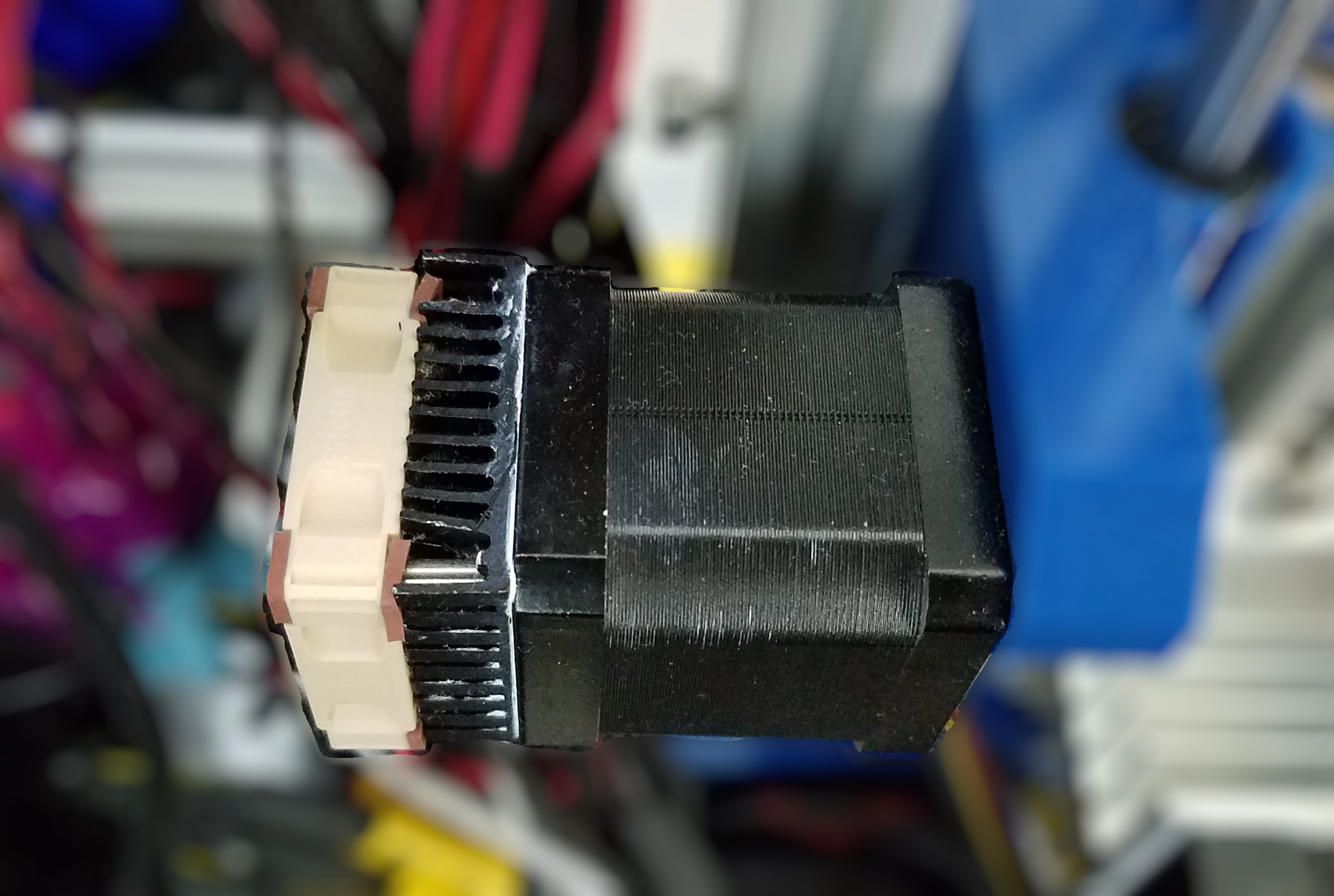
- Stack the motor, heat sink (flat side facing the motor), and fan (in that order) with the holes in the heat sink lined up with the screw holes from the screws you removed.
- Screw the new assembly down using the elongated screws.
- Stand back and admire a motor that will be almost impossible to overheat without burning up your drivers first.